

Selecting the right rotor for your screw pump system is one of the most important engineering
decisions in any positive displacement pumping application. The rotor directly influences
flow stability, volumetric efficiency, energy consumption, wear rate, noise level, and the
long?term reliability of the screw pump. This comprehensive guide explains how to choose a
screw pump rotor based on fluid properties, operating conditions, materials, geometry and
performance requirements.
In a screw pump, the rotor is the helical element that converts rotational motion into
axial movement of the fluid. The rotor works together with matching stators, liners or
housing bores to form sealed cavities that move the pumped medium from suction to discharge.
A screw pump rotor can take several forms:
Because the rotor is the main power-transmitting and sealing element in the screw pump,
choosing the correct rotor is essential for pump performance, reliability and service life.
Screw pump rotors create a series of enclosed, progressing cavities. As the rotor or rotors turn:
The quality of sealing along the rotor, the accuracy of rotor geometry, and the rotor material’s
compatibility with the process fluid together determine the volumetric efficiency and wear rate
of the screw pump.
The right rotor for a screw pump system can:
Conversely, a poorly chosen rotor can lead to accelerated wear, cavitation, frequent
shutdowns, contamination, product degradation, and unexpected failures.
Screw pump technology covers several rotor concepts. Understanding these categories is
the first step in choosing the right rotor for your screw pump system.
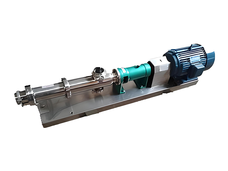
A progressive cavity screw pump (often simply called a progressive cavity pump or PC pump)
uses a single metal rotor with one or more external helices turning inside an elastomer stator
with a matching internal helix pattern. The rotor and stator form cavities that progress along
the axis as the rotor turns.
Typical characteristics of progressive cavity rotors:
Twin screw pumps use two intermeshing, counter-rotating screws. Each rotor has helical
lobes that mesh with those on the other rotor. The screws rotate within a close-fitting housing.
Typical features of twin screw rotors:
Triple screw pumps employ three intermeshing rotors: a central power rotor driving two
idler rotors. The screws are usually contained within a closely machined barrel.
Typical features of triple screw rotors:
Some applications use multi-screw designs beyond three screws or with optimized special
rotor profiles to achieve higher capacities, improved suction properties, or reduced noise.
These are more specialized and typically custom-engineered for demanding process duties.
| Rotor Type | Number of Rotors / Screws | Typical Fluids | Viscosity Range | Pressure Range (Typical) | Key Advantages |
|---|---|---|---|---|---|
| Progressive cavity rotor | 1 rotor + elastomer stator | Slurries, sewage, polymer solutions, food pastes, chemicals | Medium to very high viscosity, solids-laden | Up to ~48 bar (can be higher with multi-stage) | Handles abrasives & solids, gentle pumping, good suction lift |
| Twin screw rotors | 2 screws (counter-rotating) | Food, beverages, pharma, multiphase fluids | Very wide range from low to very high | Up to ~25–40 bar, depending on size | Low pulsation, hygienic, CIP-capable, non-contacting profiles |
| Triple screw rotors | 3 screws (1 drive + 2 idlers) | Lubricating oils, fuel oil, hydraulic fluid | Low to medium viscosity, lubricating | Up to ~100 bar or more | High pressure, smooth flow, compact, quiet operation |
| Special multi-screw rotors | 3+ screws, custom profiles | High capacity process streams, transfer duties | Medium to high viscosity | Application-specific | Custom performance, high reliability in demanding service |
Choosing the right screw pump rotor requires a systematic evaluation of process conditions,
mechanical constraints, and performance goals. The following factors should be reviewed
during rotor selection.
Fluid characteristics strongly influence rotor material, coating, and geometry:
Viscosity: Highly viscous fluids may require slower speeds and larger rotor
pitch. Low-viscosity fluids may demand tighter clearances and improved surface finishes
to reduce internal leakage.
Solids content: Size, shape and concentration of solids determine the
acceptable rotor-to-stator or rotor-to-housing clearances and material hardness.
Corrosiveness: pH, chlorides, sulfides and other corrosive agents drive
the choice of rotor base material and any protective coatings.
Lubricity: Poorly lubricating media (e.g., water-like fluids) can accelerate
rotor wear in triple screw pumps designed for lubricating oils.
Temperature: High or low temperatures affect material selection, clearances
and thermal expansion, especially when metallic rotors run inside elastomer stators.
Required discharge pressure and allowable differential pressure per stage influence the rotor design:
Rotor designers must balance pressure capability with mechanical strength, stiffness,
and manufacturing tolerances.
Flow rate is roughly proportional to rotor speed in screw pumps, but speed is limited by:
Rotor geometry (diameter, pitch, number of starts) must be chosen to meet flow requirements
at acceptable rotational speeds.
Poor suction conditions or low Net Positive Suction Head (NPSH) require rotor designs with
improved suction performance:
In food, beverage, cosmetic and pharmaceutical applications, rotor selection must comply with
hygienic standards and regulatory requirements:
Rotor selection also affects the total cost of ownership:
Environmental regulations and safety standards may restrict certain rotor materials or
coatings and influence the design of shaft seals, bearings and drive transmission that
interact with the rotor assembly.
Rotor material selection is a central part of choosing the right rotor for a screw pump system.
The rotor must provide sufficient strength, wear resistance and corrosion resistance while
being economically viable and machinable to the necessary tolerances.
| Material Type | Typical Grade Examples | Key Properties | Typical Applications |
|---|---|---|---|
| Carbon steel | C45, 1045, 4140 | Good strength, economical, moderate corrosion resistance when coated | Non-corrosive oils, lubricants, fuels with inhibitors |
| Alloy steel | 4140, 4340, 42CrMo4 | High strength, good fatigue resistance, can be induction hardened | High-pressure triple screw rotors, demanding mechanical loads |
| Stainless steel | 304, 316/316L, duplex grades | Excellent general corrosion resistance, hygienic, weldable | Food, beverage, chemical, wastewater, mildly abrasive slurries |
| Duplex / Super duplex | 2205, 2507 | High strength, superior pitting and crevice corrosion resistance | Chloride-bearing seawater, aggressive chemical services |
| Special alloys | Hastelloy, Inconel, Monel | Outstanding corrosion resistance in extreme media | Highly corrosive chemicals, high-temperature corrosive fluids |
To improve wear and corrosion resistance, screw pump rotors frequently receive
surface hardening or coatings:
Nitriding: Thermochemical treatment that diffuses nitrogen into the
surface of alloy steels, increasing hardness and fatigue strength without changing
the core properties.
Chromium plating: Hard chrome improves wear and corrosion resistance
and reduces surface roughness. Careful quality control is needed to avoid flaking or cracking.
HVOF and thermal spray coatings: High Velocity Oxy-Fuel (HVOF) and
other thermal spray processes apply hard, dense coatings such as tungsten carbide,
chromium carbide or ceramic layers.
Nickel-based coatings: Electroless nickel or nickel composite coatings
provide corrosion resistance and controlled hardness, often used in chemical service.
| Service Condition | Recommended Rotor Base Material | Typical Surface Treatment |
|---|---|---|
| Non-corrosive, lubricating oil | Carbon or alloy steel | May be nitrided or uncoated |
| Mildly corrosive fluids | Stainless steel (316/316L) | Polished surface, optional light hardening |
| Abrasive slurry with sand or solids | Alloy steel or stainless steel | Hard-facing, HVOF carbide coating, nitriding |
| Chloride-rich seawater | Duplex or super duplex stainless steel | Polished or passivated surface |
| Strong acids or chemicals | High-nickel alloy (e.g., Hastelloy) | Chemically resistant coating where applicable |
Rotor materials must be matched with stator elastomers or metallic housings:
Avoid combinations that cause galvanic corrosion between rotor and housing materials.
Ensure rotor hardness is compatible with stator material to avoid excessive wear
on one component.
In hygienic twin screw designs, both rotor and housing often use highly polished stainless steel.
Rotor geometry—diameter, pitch, helix angle, and number of starts—has a major impact on
performance, efficiency and operating range of screw pumps.
Rotor diameter affects displacement per revolution and mechanical strength:
Pitch is the axial distance between repeating rotor profiles. Helix angle is the angle
of the rotor thread relative to the pump axis.
The number of rotor starts (single start, double start, etc.) influences cavity formation:
Accurate control of rotor clearances and tolerances is critical:
Rotor geometry decisions require balancing:
| Rotor Geometry Change | Effect on Flow | Effect on Pressure Capability | Effect on Wear / Reliability |
|---|---|---|---|
| Increase diameter | Higher displacement per rev | Potentially higher pressure (if wall thickness & stiffness are adequate) | Higher mechanical load; may require stronger material |
| Increase pitch | Higher flow per revolution | Reduced sealing length; may lower pressure capability | Can increase speed for same flow; affects wear |
| Add more starts | Smoother flow, more cavities | Varies based on profile; typically good pressure capability | More complex manufacturing, but smoother torque profile |
| Reduce clearance | Improved volumetric efficiency | Better pressure build-up | Higher risk of contact and wear, especially with solids |
Proper rotor sizing ensures that the screw pump operates within a safe and efficient
range for the intended duty.
The rotor displacement per revolution is chosen to deliver the required flow rate at
an acceptable rotational speed. Key steps:
The maximum permissible speed of a screw pump rotor is governed by:
For progressive cavity rotors, lower speeds are typically preferred for abrasive or
solids-laden media to protect the stator and rotor surfaces.
Rotor size and design must sustain the required differential pressure without exceeding
power and torque limits:
Screw pump systems often need a wide operating range. Rotor selection should:
This section links typical industrial applications to screw pump rotor choices.
While actual selection must be based on detailed engineering, these guidelines
illustrate typical rotor selections.
Oil and gas applications include multiphase production, crude transfer, fuel handling,
and lube oil systems.
Multiphase fluids with gas and oil: Twin screw rotors with robust
profiles, often in stainless or alloy steel, provide good gas-handling capability.
Lube and fuel oil: Triple screw rotors in hardened carbon or alloy
steel are common for high pressure and smooth flow.
Produced water with solids: Progressive cavity rotors in wear-resistant
alloy with protective coatings are suitable.
Chemical applications often involve corrosive, viscous or hazardous media.
Hygienic applications require rotors designed for cleanability and product protection:
Pulp, paper and wastewater applications often handle fibrous materials and abrasive solids:
In power plants and marine systems, screw pumps are used for fuel oil, lube oil and hydraulic systems:
Understanding common screw pump rotor problems and their root causes helps optimize rotor
selection and operation.
| Observed Issue | Likely Cause | Rotor-Related Corrective Action |
|---|---|---|
| Rapid wear or scoring | Abrasive particles, insufficient hardness, inadequate lubrication | Select harder rotor material or coating; adjust clearances; reduce speed; improve filtration |
| Corrosion or pitting | Incompatible material with process fluid | Change to corrosion-resistant alloy or apply protective coating |
| Loss of pressure / internal slip | Excessive wear, incorrect clearances, high temperature expansion | Replace worn rotor; tighten clearances within limits; select materials with better thermal match |
| Vibration and noise | Unbalanced rotor, rotor contact, misalignment or cavitation | Rebalance rotors; check tolerances; optimize rotor geometry for NPSH; ensure correct installation |
| Stator or housing damage | Rotor contacting stator or bore due to deflection or thermal growth | Increase rotor stiffness; adjust geometry or material; review operating pressure and temperature |
Reassessing rotor selection is appropriate when:
Once the right rotor is chosen, maintenance and proper operation are essential to
maximize screw pump rotor life and keep total cost of ownership under control.
Developing a spare rotor strategy for screw pump systems is part of overall asset management:
Advanced condition monitoring systems can track key indicators such as:
By correlating this data with rotor inspections and failures, plant operators can
refine rotor selection, operating windows, and maintenance intervals.
The following checklist summarizes key steps in choosing the right rotor for your screw pump system.
In every screw pump system, the right rotor:
By following disciplined rotor selection practices, operators and engineers ensure that
screw pump systems deliver reliable, cost-effective and energy-efficient service across
a wide range of industrial applications.
```

Copyright ? Jiangsu Longjie Pump Manufacturing Co., Ltd.


 Phone
Phone
Comment
(0)